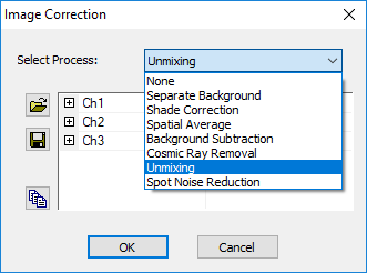
The Image Correction dialog provides the ability to enhance images using digital image processing tools. The digital image processing tools or algorithms are available through the drop-down list.

Enter level variance and minimum spot area.
If the illumination source for an image presents a bright non-uniform background, as is typical in bright field microscopy, applying a correction for this shading may be helpful for producing an image better suited for measurements.
The Shade Correction algorithm calculates a correction image in which each pixel's value is a positive integer which, when added to the corresponding pixel in the shaded image, increases intensity value of darker pixels (presumably more shaded) by a greater amount than the intensities of lighter pixels (which are presumed to have been more strongly illuminated).
| Corrected Image = (Original Image)/(Background Image) * (Mean value of all pixels in the arithmetic image) |

Enter Noise Threshold. If the gray level intensity difference between the center pixel and any of its eight direct neighbors is greater than the Noise Threshold, then the pixel is given the average gray level of its neighbors instead.
If the illumination source for an image presents a dark non-uniform background, as is typical in fluorescence microscopy, it may be necessary to apply an image background subtraction to produce an image suitable for measurement.
Choose Background Image. The Background Image is subtracted from the current image.
Note: This is different from an Image Subtraction which scales the subtracted intensities between +127 to -127 into the range of 0 to 255, indicating loss or gain of intensity.
Enter Threshold and Dilation values (number of dilation passes: d.)
Mask original image from threshold value to max gray value.
Dilate mask by d passes – Looking to encompass non-thresholded rise around ray.
Measure the diameter in the mask image. Find the radius of the ray: r. Apply Median from original to destination for r passes – passes should be half-diameter of ray.
Conditional copy of original outside mask to replace non-masked values with original data
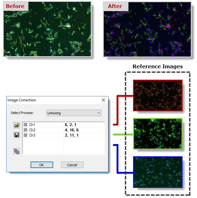
Spectral Unmixing uses an algorithm to create a matrix to correct the overlapping of multiple fluorescent signals. For example, the emission spectra of fluorochromes CFP, YFP and GFP strongly overlap with one another. In addition to the Source image, Reference images for each fluorochrome used are required. Each fluorochrome reference image must be acquired using all of the emission filters; i.e., a single excitation captured with multiple emission filters. The reference images must be captured under the exact conditions as the source image (i.e., exposure, gain, binning, bit-depth, etc.) or the resultant image is black with zero data. The order of the reference images is important, Reference 1 = Red, Reference 2 = Green, Reference 3 = Blue.
Click on the Calculate Matrix from Control Images button ( ) to load the reference images and calculate the matrix. The matrix can be saved and reloaded for future use by clicking on the Save and Open buttons.

The Spot Noise Reduction algorithm removes noise in an image by comparing multiple images in a data set based on the following criteria:
Comparison Image
Threshold Type
Amount